Network Architecture
ZEROBASE Prover Network Architecture
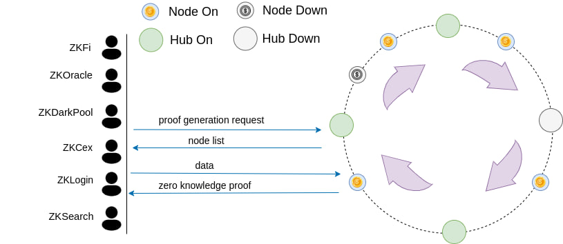
In the network architecture of ZEROBASE Prover Network, each node is assigned to a specific subset, and its corresponding Hub is responsible for maintaining the status information. Through this mechanism, each Node only communicates with its designated Hub, which effectively reduces the communication overhead and management complexity of the system, while improving the overall operation efficiency. Under this architecture, even if the number of Nodes increases significantly, the system can still maintain stable operation by dynamically adding Hubs to ensure the efficiency and scalability of the network. In addition, when a Hub fails or fails, other Hubs can take over the Nodes it manages, thereby ensuring the high availability and robustness of the network.
In order to further improve the security and credibility of the network, all Nodes must complete the pledge operation before joining the network. This mechanism not only ensures that the Node complies with the protocol specifications, but also effectively prevents potential malicious behavior and enhances the security protection capabilities of the entire system.
ZEROBASE Prover Network serves as a foundational infrastructure for a wide range of zero-knowledge-based applications, enabling efficient and scalable proof generation across various cryptographic use cases, such as ZKCex, ZKDarkPool, and ZKLogin.
Node Partitioning
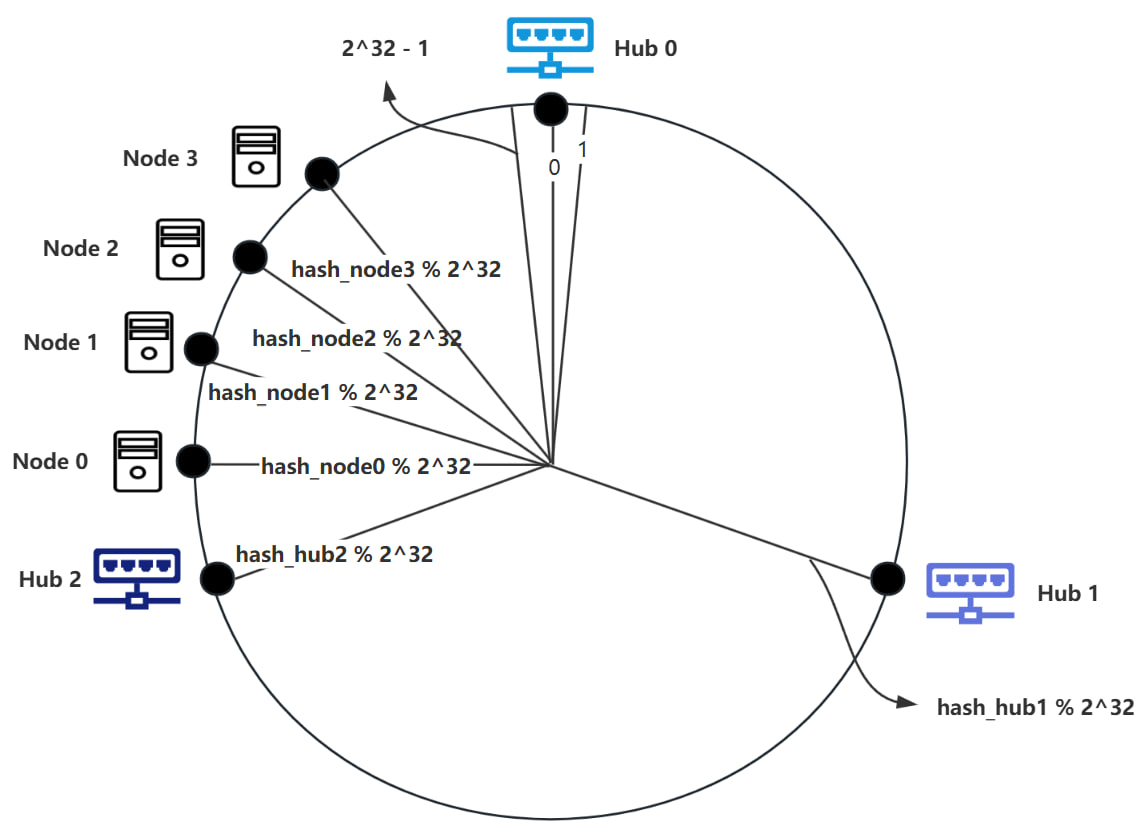
The Node partitioning is based on a consistent hashing algorithm. We will explain this algorithm with an example. Suppose there are currently 3 Hubs and n Nodes. We need to allocate the Nodes to different Hubs. First, we number the 3 Hubs as Hub0, Hub1, and Hub2, and arrange them clockwise on a circle. Imagine this circle as a clock with ticks, where the minimum tick is 0 and the maximum tick is . By hashing the IP address of Hub0, we get hash_hub0 = Hash(IP), Hub0 is positioned at hash_hub0 % on the clock. Similarly, we can calculate the positions of Hub1 and Hub2 using the same method, as shown in the diagram below.
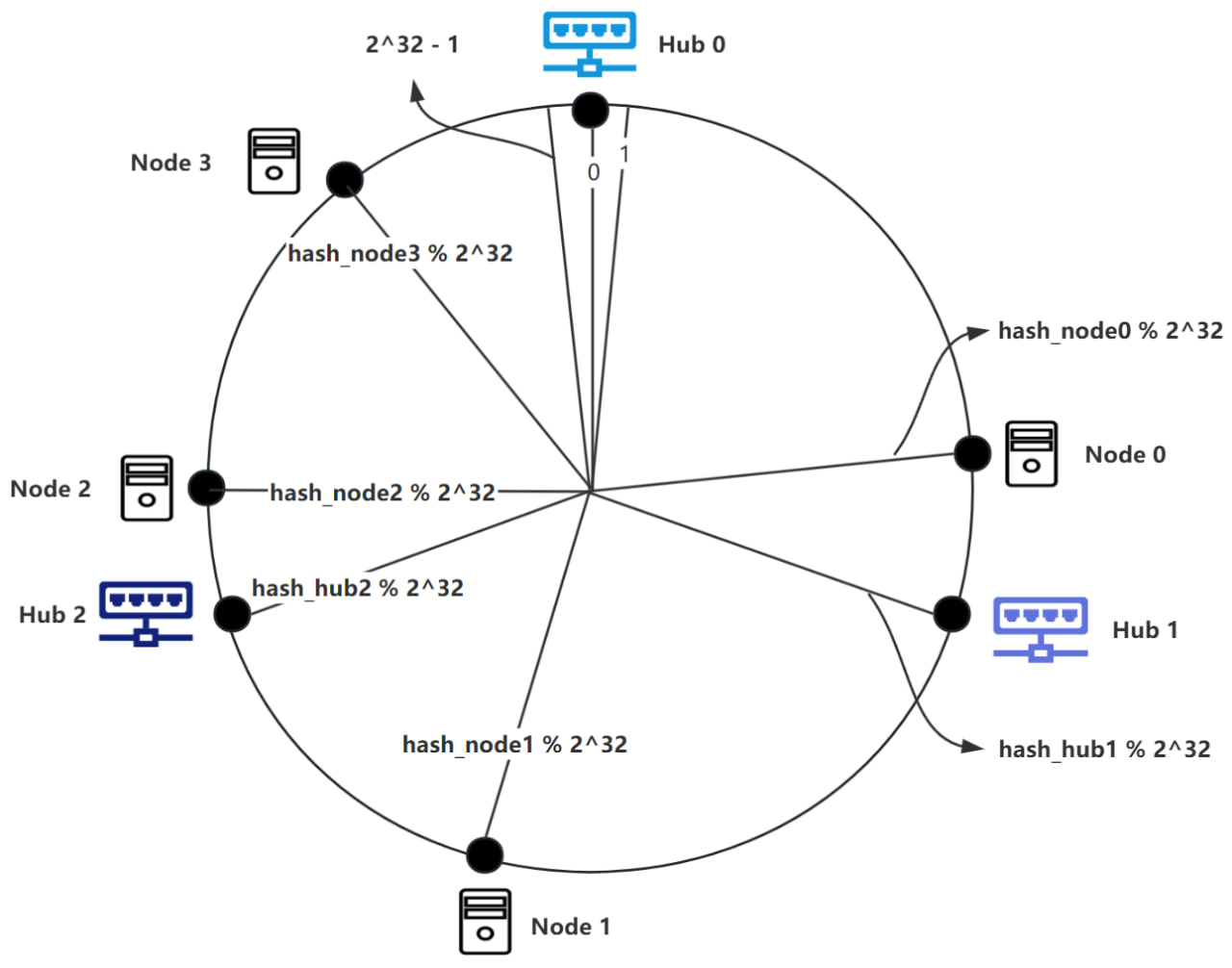
In the diagram above, the position of Hub0 is at tick 0, with the tick to the left of Hub0 being and the tick to the right of Hub0 being 1. When adding a new Node0, we hash Node0's IP and port to get hash_node0 = Hash(IP, Port), which serves as Node0’s identifier. To determine the Hub corresponding to Node0, we place Node0 at the position hash_node0 % on the clock. The Hub corresponding to Node0 is the first Hub encountered moving clockwise from Node0’s position, as shown in the diagram below.
In the diagram above, a total of 4 Nodes have been added, and their computed positions are shown. According to the rules, Hub0 is responsible for Node2 and Node3; Hub1 is responsible for Node0; and Hub2 is responsible for Node1.
Adding Hubs
When the number of Nodes becomes excessive, resulting in a high load on the Hub, additional Hubs can be introduced to maintain optimal system performance. The process is as follows: when a new Hub (Hub3) is to be added, the IP address of Hub3 is hashed to yield hash_hub3=Hash(IP). Hub3 is then positioned on a scale corresponding to hash_hub3 % , as illustrated in the diagram below.
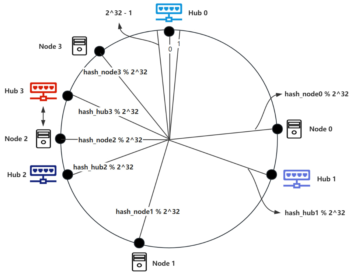
Given the addition of Hub3, it is necessary to reallocate Nodes according to the established Node partitioning rules. As shown in the diagram, the Node corresponding to Node2 must be transitioned from Hub0 to Hub3.
Removing Hubs
If a Hub fails, it is essential to ensure the continued operation of the Nodes it was responsible for by reallocating those Nodes to other Hubs. The process is as follows: when Hub1 fails, it is first removed from the ring. Additionally, Node0 must be reassigned to Hub2, as depicted in the diagram below.
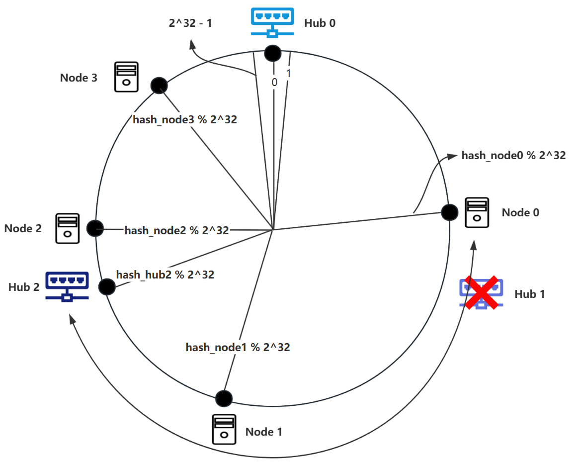
Through the use of a consistent hashing algorithm, only a small portion of Nodes within the ring space needs to be reassigned. The remaining Nodes stay unchanged. As the number of Hubs increases, the impact on the number of Nodes affected by the addition or removal of Hubs decreases. Consequently, this architecture demonstrates robust fault tolerance and scalability.
Virtual Nodes
In certain scenarios, the randomness inherent in hashing algorithms can lead to a critical issue: data skew, where a majority of Nodes are allocated to a limited number of Hubs. This problem is particularly pronounced when the number of Hubs is low, as uneven distribution of Hubs around the ring can result in load imbalance. Consider the following situation: we have three Hubs (Hub0, Hub1, Hub2) and four Nodes (Node0, Node1, Node2, Node3). According to the aforementioned Node partitioning rules, we might observe the following allocation.
When the number of Hubs is insufficient, the spacing between Hubs may be too great, leading to a concentration of Nodes between just two Hubs. As illustrated, according to the Node partitioning rules, Nodes 0, 1, 2, and 3 are all assigned to Hub0, while Hub1 and Hub2 are not allocated any Nodes. In this case, the entire distributed architecture regresses to a centralized structure. To address this issue, a virtual node mechanism can be introduced.
Operational Mechanism
To mitigate the load imbalance among different Hubs caused by data skew, we can map each Hub to multiple virtual nodes. The established Node partitioning rules are then applied to allocate Nodes to these virtual nodes. When a Node communicates with its assigned virtual node, it effectively communicates with the Hub corresponding to that virtual node.
For example, consider the scenario with three Hubs (Hub0, Hub1, Hub2) and four Nodes (Node0, Node1, Node2, Node3). Each Hub (Hubi) is virtualized into two instances (Hubi0 and Hubi1). This results in the following nodes: Hub00, Hub01, Hub10, Hub11, Hub20, Hub21, Node0, Node1, Node2, and Node3. Using the previously established rules, we allocate the Nodes as follows: Node0 and Node1 are assigned to Hub01, which corresponds to Hub0, thus they are effectively allocated to Hub0; Node2 is assigned to Hub10, corresponding to Hub1; hence Node2 is allocated to Hub1; Node3 is assigned to Hub21, which corresponds to Hub2, so Node3 is allocated to Hub2.